
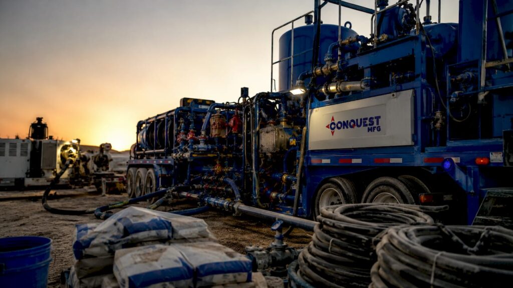
Oil well cementing is defined as the process of pumping a specialized cement slurry into the annular space between the casing and the wellbore wall to form a solid, impermeable barrier. The oilfield cementing process explained in full covers far more than mixing and pumping. It spans slurry engineering, mud displacement, pipe centralization, and flow control, all working together to achieve zonal isolation and long-term well integrity. Industry standards like API Spec 10A govern cement classification and performance requirements, making this one of the most regulated operations in well construction. Get it wrong, and the consequences reach well into the millions.
What are the key stages in the primary cementing process?
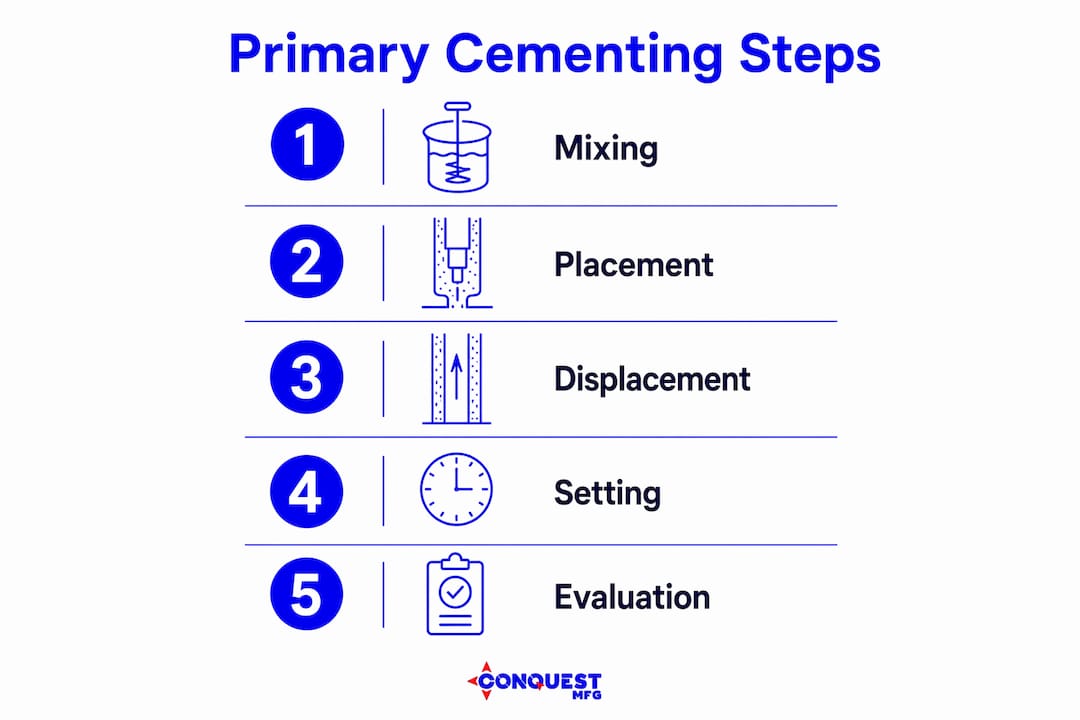
Primary cementing is the industry default for cased-hole completions. The goal is to place cement in the annulus between the casing string and the formation in a single, continuous operation. Every stage must be sequenced correctly, because errors compound downward.
The process follows this operational order:
- Pre-job hydraulic modeling. Engineers simulate the full displacement sequence before any fluid enters the well. This modeling integrates mud properties, spacer rheology, slurry density, and pump rates to predict annular flow behavior across every depth interval.
- Mud conditioning. The drilling fluid is circulated and conditioned to reduce gel strength and improve its displacement by the spacer. Poorly conditioned mud resists removal and creates channels in the cement sheath.
- Spacer and pre-flush pumping. A chemical spacer is pumped ahead of the cement slurry. The spacer separates the mud from the slurry, conditions the pipe and formation surfaces, and must maintain turbulent flow during displacement to scour mud cake from the wellbore wall.
- Cement slurry placement. The slurry is pumped through the cementing head and down the casing. A bottom plug precedes the slurry to wipe the casing ID clean. A top plug follows the slurry and signals displacement completion when it seats on the float collar.
- Displacement and bump. Drilling fluid or water displaces the slurry up the annulus. The top plug “bumps” at the float collar, confirming the job is complete. Pressure is held until the cement achieves initial set.
- Wait on cement (WOC). The well is shut in while the cement develops compressive strength. WOC time depends on bottomhole temperature and slurry design.
Pro Tip: Monitor plug indicator flags on the cementing head throughout the job. Plug indicator flags and quick latch integrity are key monitoring components, and a missed flag can mean the top plug was never launched, leaving the annulus unprotected.
How is cement slurry formulated for downhole conditions?
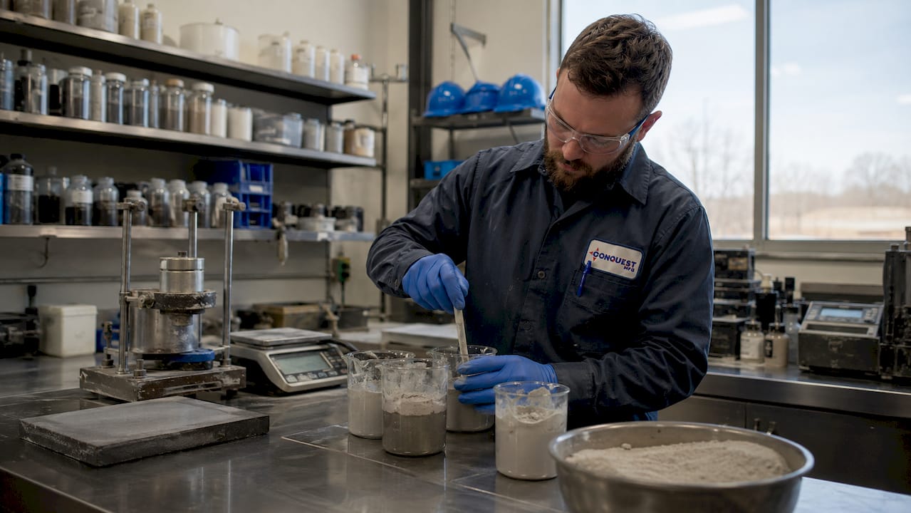
Oil well cement is not ordinary Portland cement. API Spec 10A classifies oil well cements for applications up to 16,000 ft depth, with manufacturing processes that expose clinker to temperatures up to 3,000°F to produce the required mineralogy. That thermal history gives oil well cement the density, permeability, and chemical resistance that construction cements cannot match.
Slurry formulation starts with selecting the right API class cement for the depth and temperature range. From there, additives are blended to meet specific downhole conditions:
- Retarders extend thickening time so the slurry remains pumpable from surface to total depth without premature setting.
- Dispersants reduce slurry viscosity, improving pumpability and displacement efficiency without adding water.
- Fluid-loss control agents prevent the slurry from dehydrating against permeable formations, which would cause bridging and incomplete placement.
- Gas-migration control polymers reduce the transition time between liquid and solid states, closing the window during which formation gas can migrate through the slurry column.
- Accelerators shorten WOC time in shallow, low-temperature wells where early compressive strength is needed quickly.
Hydrostatic pressure management is equally critical. The slurry column must maintain enough pressure to prevent formation fluid influx during placement, but not so much that it fractures weak zones. This balance drives density selection and slurry volume calculations for every stage of the job.
What challenges affect fluid flow during cement placement?
Fluid flow behavior inside the annulus is the most underestimated variable in cementing design. Surface-controlled pump schedules alone cannot ensure uniform displacement or prevent channeling. The annulus is not a uniform pipe. It has irregular geometry, varying standoff, and zones of different permeability that all influence how fluids move.
The core challenges include:
- High-side/low-side separation. In deviated wells, gravity pulls denser fluids to the low side of the annulus. Cement can bypass mud on the high side, leaving uncemented channels that become migration pathways.
- Laminar flow channeling. At low pump rates, flow is laminar and follows the path of least resistance. Mud in tight annular gaps stays in place while cement flows around it.
- Velocity profile non-uniformity. Even in vertical wells, poor centralization creates narrow gaps where fluid velocity drops below the threshold needed to displace mud.
- Fluid separation and slurry instability. Free water separation from an unstable slurry creates a water channel at the top of the cement column, weakening the sheath and creating a leak path.
Pipe standoff is the most critical physical factor for displacement efficiency. Below 70% standoff, even a well-designed slurry cannot achieve complete mud removal. Centralizer placement modeling targets 70% standoff across producing zones and 80% in critical intervals. These thresholds are based on displacement efficiency analyses showing that the lowest standoff intervals produce the highest mud remnants.
Mechanical flow control tools address what pump schedules cannot. Scratchers, centralizers, and turbulators mounted on the casing string physically agitate mud and improve annular velocity distribution. These tools are not optional in deviated or extended-reach wells. They are the difference between a cemented annulus and a channeled one.
Pro Tip: Run a pneumatic cementing system with real-time pressure monitoring to catch anomalies during displacement. A sudden pressure drop during pumping often signals a lost circulation event or plug failure before it becomes a full job loss.
What alternative zonal isolation methods exist beyond primary cementing?
Primary cementing is the first choice, but it is not always the right one. Zonal isolation techniques are categorized into five primary families, each suited to different well conditions and completion objectives.
| Isolation method | Best use scenario | Key limitation |
|---|---|---|
| Primary cement | Cased-hole completions, all depths | Channeling risk in deviated wells |
| Mechanical packers | High-pressure gas zones, workover operations | Requires reliable anchor point |
| Swellable elastomer packers | Open-hole completions, tight-gas reservoirs | Activation time depends on fluid type |
| Bridge plugs | Temporary or permanent zone abandonment | Single-zone isolation only |
| Hybrid cement + packer | Critical intervals with high gas migration risk | Higher cost and complexity |
Swellable elastomer packers are particularly useful in open-hole completions where running casing and cementing would damage the formation or cause filtrate invasion. The elastomer expands on contact with hydrocarbons or water, creating a mechanical seal without any pumped fluid. Mechanical packers provide immediate, verifiable isolation in workover operations where re-cementing is not practical.
Hybrid configurations combine cement with mechanical elements to address the limitations of each method alone. A packer set above a perforated interval, combined with a cement plug below, creates redundant isolation that neither method achieves independently. This approach is standard in high-pressure gas wells where a single barrier failure carries significant risk.
How does the PWC technique improve abandonment operations?
The Perforate, Wash, and Cement (PWC) technique is the most operationally efficient method for plug and abandonment in deepwater wells. PWC allows sequential operations including casing communication, annular cleaning, and cementing using a single bottomhole assembly, which eliminates multiple tool runs and the associated rig time costs.
The sequence works as follows:
- Perforate. The tool perforates the casing at the target depth, creating communication between the casing interior and the annulus. This step confirms that the annular space is accessible for cleaning.
- Wash. A wash fluid is circulated through the perforations to remove mud, scale, and debris from the annulus. Effective washing is the prerequisite for cement bonding. Skipping or shortcutting this step is the most common cause of PWC job failure.
- Cement. Cement slurry is pumped through the same perforations to fill the cleaned annulus. The single BHA placement means the cement enters the annulus at exactly the depth where washing was confirmed.
PWC has become an essential practice for deepwater abandonment projects, particularly in the subsalt plays offshore Brazil. The technique reduces the number of BHA runs from three to one, cutting rig time significantly on wells where day rates run into the hundreds of thousands of dollars. Technical adaptations for deepwater include high-density spacers to manage hydrostatic pressure at depth and temperature-corrected retarder schedules to account for the cold seabed environment.
Key Takeaways
Effective oilfield cementing requires integrating slurry design, pipe centralization, spacer engineering, and mechanical flow control into a single pre-job plan, because any one of these factors failing alone is enough to compromise the entire cement sheath.
| Point | Details |
|---|---|
| Centralization is non-negotiable | Target 70% standoff minimum; below this threshold, mud removal fails regardless of slurry quality. |
| Spacer design drives displacement | The spacer must maintain turbulent flow and chemical compatibility; inadequate design causes over 60% of primary cementing failures. |
| API Spec 10A sets the baseline | Oil well cement must meet API Spec 10A classifications; ordinary Portland cement cannot withstand downhole temperatures, pressures, and corrosive fluids. |
| Mechanical tools fill the gap | Surface pump schedules cannot control annular flow uniformity; scratchers, centralizers, and turbulators are required in deviated wells. |
| PWC cuts abandonment rig time | The PWC technique consolidates perforation, washing, and cementing into one BHA run, reducing deepwater abandonment costs significantly. |
What I’ve learned from watching cementing jobs fail
The pattern I see most often in failed cementing jobs is not a slurry formulation error. It is a centralization shortcut taken during casing running because the rig schedule was tight. Engineers spend days optimizing additive packages and then accept 40% standoff across the producing zone because adding centralizers would slow the job down. That decision routinely costs between $250,000 and $2 million in remedial squeeze operations. The math never works in favor of the shortcut.
The second pattern is spacer design treated as an afterthought. The spacer is not just a buffer fluid. It is the active displacement agent that conditions the wellbore for cement bonding. When the spacer volume is undersized or its rheology is not matched to the mud and slurry it sits between, the entire displacement sequence breaks down. No amount of pump rate adjustment at surface recovers from a poorly designed spacer.
What I find genuinely encouraging is the direction the industry is moving with digital pre-job modeling and integrated hydraulics simulation. Teams that run full displacement simulations before the job, including sensitivity cases for standoff variation and pump rate changes, catch problems on a laptop that used to show up as sustained casing pressure six months after completion. The oilfield material handling side of the operation matters too. Cement delivered to the wellsite in poor condition, with moisture contamination or incorrect classification, undermines every engineering decision made upstream. The whole system has to work.
— Sam
Conquest Mfg equipment for oilfield cement operations
Reliable cementing starts before the first pump stroke. It starts with how cement is stored, transported, and batched at the wellsite.
Conquest Mfg manufactures portable cement pig silo trailers, dry bulk pneumatic trailers, and stationary and mobile batch plants for oilfield use that give cementing crews consistent, contamination-free slurry production in the field. For bulk cement transport, Conquest Mfg’s pig silo trailers are built to handle the volume and delivery precision that oilfield cementing operations demand. Every unit is designed for the conditions professionals actually work in, not laboratory ideals. Contact Conquest Mfg to spec the right equipment for your next cementing program.
FAQ
What is the primary objective of oil well cementing?
Oil well cementing creates zonal isolation between formation intervals and supports the casing string structurally. Without an effective cement sheath, formation fluids can migrate between zones or reach surface.
Why does pipe centralization matter so much in cementing?
Below 70% standoff, mud removal becomes incomplete regardless of slurry design or pump rate. Centralizer placement modeling targets 70–80% standoff across critical intervals to achieve reliable displacement efficiency.
What causes most primary cementing failures?
Inadequate centralization and poor spacer design cause over 60% of primary cementing failures, leading to sustained casing pressure or cross-flow between zones.
How does oil well cement differ from ordinary Portland cement?
Oil well cement meets API Spec 10A requirements for high temperature, pressure, salinity, and corrosive fluid resistance. Ordinary Portland cement lacks the mineralogy and density control needed for downhole conditions at depths up to 16,000 ft.
When is the PWC technique used instead of conventional cementing?
PWC is used primarily in plug and abandonment operations, especially in deepwater wells where running separate tool strings for perforation, washing, and cementing would multiply rig time and cost. It consolidates all three operations into a single BHA run.