
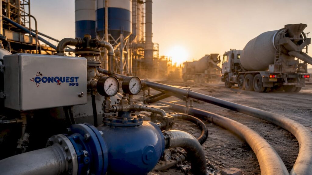
Pneumatics power the mechanical systems that make oilfield cementing accurate, safe, and repeatable. The role of pneumatics in oilfield cement spans every phase of the process, from transporting bulk dry cement out of silos to actuating blowout preventer controls during critical well preparation. Industry standards like API Spec 16D mandate pneumatic backup systems in well control equipment, which signals how foundational this technology is to drilling safety. Engineers who understand how pneumatic systems in oilfield environments work can prevent costly failures, maintain slurry consistency, and protect crews from avoidable hazards.
How pneumatic systems automate bulk cement handling and slurry mixing
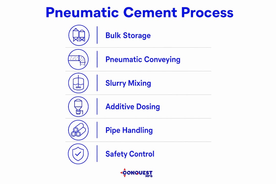
Pneumatic conveying systems are the standard method for moving bulk dry cement from storage silos to mixing units in oilfield operations. Pressurized air carries cement through enclosed pipelines, which eliminates dust exposure, prevents contamination, and delivers material at a controlled, continuous rate. That clean delivery is not just a convenience. It directly affects slurry quality by keeping the cement dry and free of foreign material before it reaches the mixer.
Once cement reaches the mixing stage, pneumatic cylinders take over the dosing and discharge functions. Cylinders compliant with ISO 15552 automate the opening and closing of silo discharge gates and regulate the flow of chemical additives into the slurry. Standardized pneumatic components ensure compliance with safety directives like 2006/42/EC under abrasive, high-load conditions. That compliance matters in oilfield environments where equipment faces constant vibration, pressure swings, and corrosive materials.
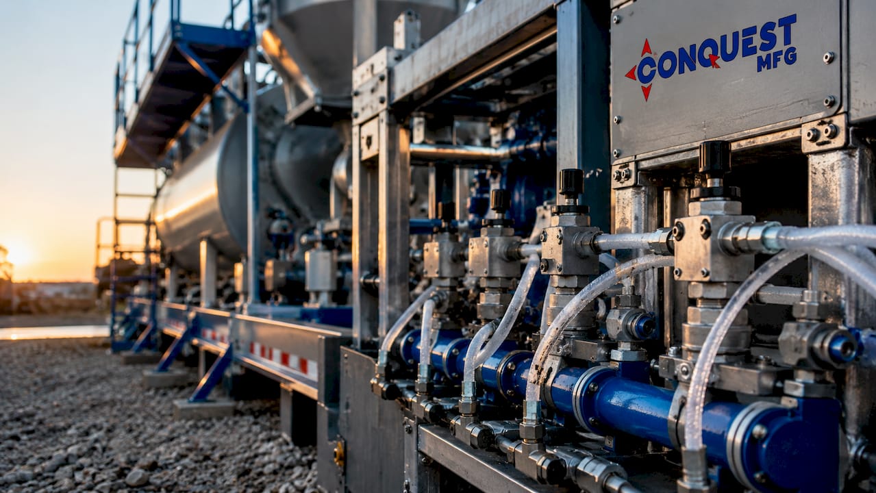
Maintaining a precise cement-to-water ratio is the single most important factor in producing a reliable wellbore cement sheath. Pneumatic automation holds that ratio steady by removing the variability of manual handling. Automated density control through pneumatic conveying allows real-time adjustments that prevent weak zones from forming in the cement column.
| Component | Function in cement handling |
|---|---|
| Pneumatic conveying line | Moves bulk dry cement from silo to mixer without contamination |
| ISO 15552 pneumatic cylinder | Automates silo gate discharge and additive dosing |
| Pressure regulator | Maintains consistent airflow for uniform material delivery |
| Air compressor and dryer | Supplies clean, dry compressed air to all system components |
| Local accumulator | Stores pressurized air for rapid actuator response during peak demand |
The table above reflects a complete pneumatic cement handling circuit. Each component depends on the others. A failed regulator, for example, disrupts dosing accuracy across the entire system.
What pneumatic tools and equipment support cementing safety during drilling?
Pneumatic spiders and slips are the primary pipe handling tools used during casing and tubing operations that precede cementing. A pneumatic spider automates slip engagement, supporting load capacities from 100 to 1,500 tons at operating pressures of 0.6–0.8 MPa. That range covers virtually every casing size used in modern drilling programs. Automating slip engagement removes the need for manual tong work at the rotary table, which is one of the highest-risk tasks in well preparation.
Pneumatic backup pumps serve a different but equally critical function. API Spec 16D requires pneumatic backup pumps in blowout preventer control units to maintain hydraulic fluid pressure if primary power fails. BOP pneumatic backup systems act as a fail-safe, ensuring rapid closure of the preventer even during a complete electrical or hydraulic power loss. That redundancy is not optional. It is a regulatory requirement because a delayed BOP closure during a kick can result in a blowout.
Key pneumatic tools used in oilfield cementing operations include:
- Pneumatic spiders: Engage and disengage casing slips automatically, reducing crew exposure at the rotary table
- Pneumatic slips: Grip and release tubing strings under load without manual intervention
- BOP pneumatic backup pumps: Maintain hydraulic pressure for preventer closure per API Spec 16D
- Pneumatic cement pump drives: Power cement displacement pumps where electric or hydraulic drives are impractical
- Pneumatic control manifolds: Route air pressure to multiple actuators simultaneously during complex cementing sequences
Pro Tip: Monitor supply line pressure at the tool inlet, not just at the compressor outlet. Pressure drop across long air lines is common on large rigs, and a tool rated for 0.7 MPa will underperform or fail to engage if it only receives 0.5 MPa at the point of use.
Pneumatic actuator speed and reliability depend directly on regulated pressure at the tool. Inconsistent pressure causes delayed slip engagement, which creates a safety gap during pipe handling. Local accumulators placed near high-demand tools solve this problem by providing an immediate pressure reserve.
What are the main challenges and maintenance considerations for pneumatic systems?
Moisture contamination is the leading cause of pneumatic system failures in cement conveying operations. Humidity in compressed air lines triggers premature cement hydration inside the pipeline, forming solid plugs that halt operations entirely. High-quality air filtration and desiccant dryers installed at the compressor outlet are the primary defense against this failure mode. Skipping dryer maintenance is the fastest way to schedule an unplanned shutdown.
A persistent misconception in oilfield operations is that compressed air is essentially free because it comes from the atmosphere. Compressed air generation consumes significant energy, and system leaks compound that cost while degrading pressure stability across the entire circuit. A compressor running harder to compensate for leaks wears out faster and delivers less consistent pressure to tools. The real cost of “free air” shows up in energy bills, compressor replacement cycles, and unplanned downtime.
Maintenance priorities for pneumatic systems in cementing operations:
- Inspect and replace desiccant dryer media on the manufacturer’s schedule, not just when performance degrades visibly
- Audit air lines for leaks using ultrasonic detection equipment at least quarterly
- Check pressure regulator calibration at each tool inlet before every cementing job
- Test local accumulator pre-charge pressure to confirm rapid actuator response is available during peak demand
- Verify compressor oil and filter condition weekly during active drilling programs
Pro Tip: Install pressure gauges at multiple points along your air distribution network, not just at the compressor. A single gauge at the source tells you nothing about what tools are actually receiving. Distributed monitoring catches pressure drops before they cause tool failures.
Pressure instability is the second most common operational problem after moisture contamination. Pressure regulation and local accumulators together ensure that actuators respond at the correct speed during critical cementing phases. Undersized accumulators or missing regulators are common findings during post-incident reviews on rigs where pneumatic tools failed during well control events.
How do pneumatic systems integrate with digital control to improve slurry quality?
Pneumatic cement delivery and digital monitoring work together to produce consistent slurry. Pneumatic conveying moves dry cement at a controlled rate, while digital density sensors measure the slurry in real time and send correction signals back to the pneumatic control valves. Automated pneumatic delivery paired with digital density control prevents weak zones from forming in the wellbore cement sheath. That combination is now standard practice on wells where zonal isolation is critical.
The benefits of integrating pneumatic delivery with digital control loops include:
- Uniform slurry density: Sensors detect density drift and adjust pneumatic feed rates within seconds
- Reduced additive waste: Precise dosing through pneumatic cylinders eliminates over-addition of retarders, accelerators, or fluid loss agents
- Documented quality records: Digital control systems log slurry parameters continuously, creating a traceable record for regulatory review
- Faster response to formation changes: Automated loops adjust mix ratios faster than manual intervention allows
“Operators risk incomplete slurry data if relying solely on automated pneumatic delivery without integrated digital control loops for density monitoring.” This is the core risk that engineers must address when designing cementing programs for complex wells.
The risk of over-relying on automation is real. A pneumatic system delivering cement at the correct rate does not guarantee correct slurry density if a sensor fails or a control loop is misconfigured. Digital real-time monitoring must complement pneumatic bulk handling, not simply run in parallel without active oversight. Engineers who treat the digital layer as a passive recorder rather than an active control tool miss the primary benefit of the integrated system.
Combining automated cement delivery with real-time monitoring also reduces the cognitive load on cementing crews during long displacement jobs. Operators can focus on wellbore conditions and pressure response rather than manually tracking mix ratios. That shift in attention improves both safety and job quality.
Key Takeaways
Pneumatic systems are the operational backbone of oilfield cementing, controlling cement transport, additive dosing, pipe handling safety, and well control redundancy across every phase of the job.
| Point | Details |
|---|---|
| Pneumatic conveying is standard | Pressurized air moves bulk dry cement cleanly and continuously from silo to mixer. |
| ISO 15552 cylinders automate dosing | Standardized cylinders regulate additive flow and silo discharge under high-load conditions. |
| API Spec 16D mandates pneumatic backup | BOP control units require pneumatic backup pumps to maintain well control if primary power fails. |
| Moisture is the top failure risk | Desiccant dryers and quality filtration prevent cement hydration plugs in air lines. |
| Digital integration is required | Pneumatic delivery alone cannot guarantee slurry quality without active digital density monitoring. |
What engineers consistently get wrong about pneumatic cementing systems
The assumption I see most often is that pneumatic systems are simple enough to run without dedicated attention. Engineers specify the right compressor, install the right cylinders, and then treat the system as background infrastructure. That approach works until it doesn’t, and when it fails during a cementing job, the consequences are expensive and sometimes dangerous.
The “air is free” mindset is the most costly version of this problem. I’ve watched operations teams defer compressor maintenance and ignore minor leaks for months, then face a complete system pressure collapse during a critical cement displacement. The energy and repair costs from that single event exceeded a full year of proper preventive maintenance. Compressed air is not free. It is a utility that requires the same discipline as any other power source on the rig.
The second thing engineers underestimate is the importance of training technicians on pressure dynamics, not just air supply. A technician who knows how to start a compressor but doesn’t understand accumulator pre-charge pressure or regulator drift will not catch the conditions that lead to tool failure. Pneumatic system knowledge needs to go deeper than the operator’s manual.
My recommendation for 2026 drilling programs is to treat pneumatic system audits as a pre-job requirement, not an annual formality. Check pressure at every tool inlet. Verify dryer condition. Test accumulator response. That 30-minute audit before a cementing job is the cheapest insurance available on any rig.
— Sam
Conquest Mfg pneumatic equipment for oilfield cementing
Conquest Mfg builds specialist equipment for oilfield cement applications, including dry bulk pneumatic trailers and portable cement pig silo trailers designed for field deployment in drilling environments. These units are built to handle the pressure demands, abrasive materials, and operational cycles that oilfield cementing requires.

For engineers specifying equipment for cementing programs, Conquest Mfg’s oilfield pneumatic solutions cover bulk cement transport, silo storage, and pneumatic delivery systems configured for your site conditions. Conquest Mfg also supports integration with digital monitoring setups, so your pneumatic delivery and density control work as a single system. Contact Conquest Mfg to discuss equipment specifications and lead times for your next drilling project.
FAQ
What is the role of pneumatics in oilfield cement operations?
Pneumatics power bulk cement conveying, additive dosing, pipe handling tools, and BOP backup systems throughout oilfield cementing. They provide the automated, consistent force needed to move materials and actuate safety equipment reliably.
Why are pneumatic backup pumps required in BOP control systems?
API Spec 16D mandates pneumatic backup pumps in BOP control units to maintain hydraulic pressure for preventer closure if primary electrical or hydraulic power fails. This redundancy is a regulatory safety requirement, not an optional upgrade.
What causes pneumatic system failures in cement conveying?
Moisture contamination is the leading cause. Humidity in compressed air lines triggers premature cement hydration, forming solid plugs that stop material flow. Desiccant dryers and quality filtration at the compressor outlet prevent this failure.
How do pneumatic systems improve slurry consistency?
Pneumatic conveying delivers dry cement at a controlled, continuous rate while pneumatic cylinders dose additives with repeatable accuracy. When paired with digital density sensors, the system adjusts feed rates in real time to maintain target slurry density.
What pressure range do pneumatic spiders operate at?
Pneumatic spiders typically operate at 0.6–0.8 MPa and support load capacities from 100 to 1,500 tons, covering the full range of casing and tubing sizes used in modern drilling programs.