
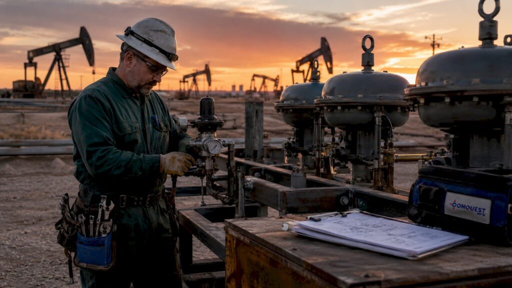
Pneumatic systems are the dominant power technology in oilfield operations because they deliver compressed air-driven actuation that is inherently explosion-proof, fast, and mechanically simple. The reason why oilfield uses pneumatic systems comes down to three non-negotiable requirements: safety in explosive atmospheres, reliable fail-safe performance, and lower total operating cost compared to hydraulic or electric alternatives. From pneumatic actuators on wellhead control panels to emergency shutdown valves (ESDVs) and blowout preventer (BOP) control units, compressed air powers the most critical functions on any oil and gas site. Understanding how these systems work and why they outperform alternatives is essential for engineers specifying equipment in 2026.
Why oilfield uses pneumatic systems: safety in hazardous zones
The single most important reason oilfields choose pneumatic systems is intrinsic safety. Pneumatic actuators carry no electrical components, which eliminates spark ignition risk entirely in ATEX Zone 1 and Zone 2 classified areas. That property alone simplifies compliance with explosion-protection regulations that govern virtually every production platform, wellhead site, and processing facility in the United States.
Safety-critical functions demand more than just spark-free operation. Pneumatic spring-return actuators achieve sub-second fail-safe closure on ESDVs without any electrical backup, battery, or external power source. That means a loss of instrument air pressure automatically drives the valve to its safe position. No command signal is needed. No power supply is required. The physics of the spring does the work.
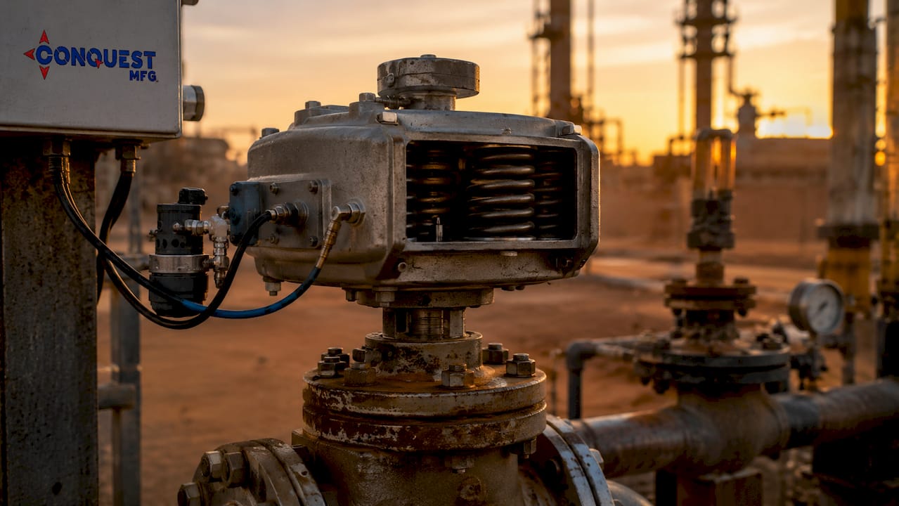
This fail-safe behavior directly supports SIL 2 and SIL 3 safety integrity levels, which are the performance benchmarks for safety instrumented systems in oil and gas. API Spec 16D mandates pneumatic-driven redundancy for BOP control units, recognizing that pneumatics deliver the response speed and independence from external power that blowout prevention demands. No electric actuator can match that combination in a Zone 1 environment without extensive and expensive explosion-proof enclosures.
Pneumatic systems also resist the physical punishment of oilfield environments. Electric systems fail more frequently in high-vibration, moisture-prone conditions, while pneumatic actuators maintain reliable operation because of their low part count and mechanical construction. Offshore platforms, land rigs, and pipeline compressor stations all subject equipment to constant vibration, humidity, and temperature swings. Pneumatics handle all three without the sensitivity that electronics carry.
Pro Tip: When specifying actuators for ATEX Zone 1 locations, always confirm that the spring-return force is sized for the maximum differential pressure across the valve, not just the nominal operating pressure. Undersized springs are the leading cause of ESDV failures during actual emergency conditions.
How do pneumatic systems compare to hydraulics and electric systems in oilfields?
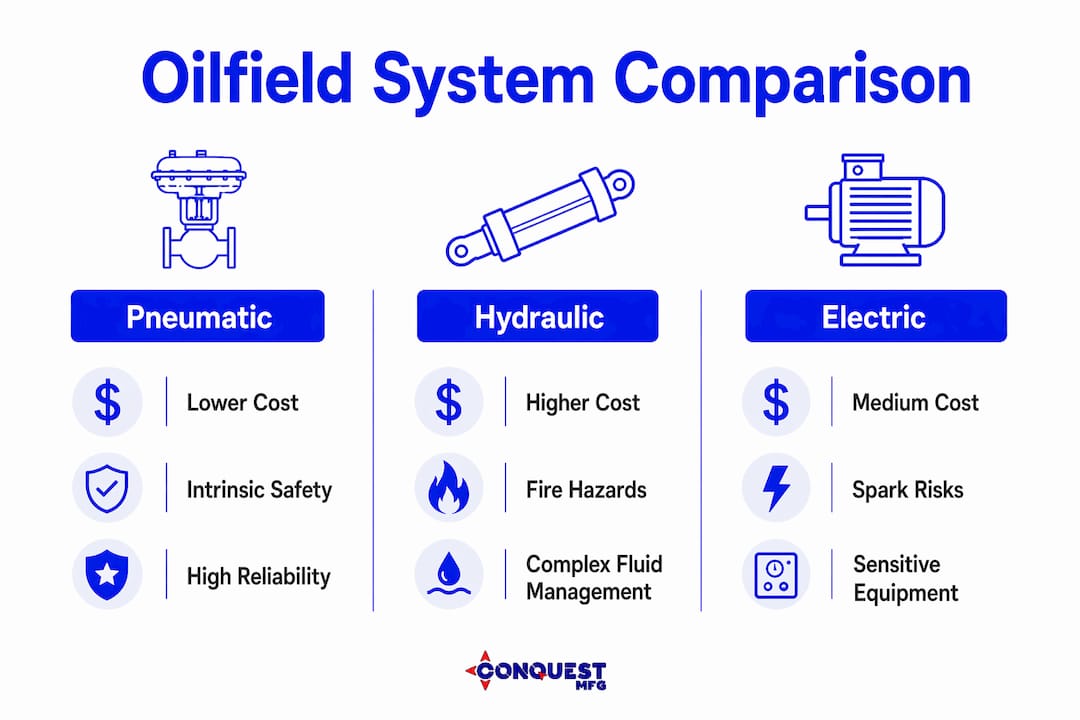
Cost and operational performance drive the preference for pneumatics across most standard oilfield applications. Pneumatic systems cost roughly half the initial installation cost of hydraulic alternatives for wellhead control applications. That gap widens when you factor in the infrastructure hydraulics require: fluid reservoirs, return lines, heat exchangers, and fluid management programs.
| Factor | Pneumatic | Hydraulic | Electric |
|---|---|---|---|
| Installation cost | Lower | Higher | Medium |
| Fire/explosion risk | None (air) | High (flammable fluid) | Moderate (sparks) |
| Fail-safe mechanism | Spring-return, no power needed | Requires accumulator | Requires battery/UPS |
| Maintenance complexity | Low | High (fluid management) | Medium |
| Response speed | Sub-second | Fast | Moderate |
| ATEX Zone 1 suitability | Inherent | Conditional | Requires Ex enclosures |
Hydraulic fluids pose fire hazards, require heavier infrastructure, and demand complex fluid management programs. Pneumatics use clean, dry air. A leak in a pneumatic line vents harmlessly to atmosphere. A leak in a hydraulic line creates a fire hazard, an environmental spill, and a maintenance event that can shut down production.
For high-cycle, load-intensive operations like tubular handling, pneumatics handle the repetitive actuation that would wear hydraulic seals and fittings far faster. Pneumatic spiders used in well servicing support loads from 100 to 500 tons while operating at 0.6–0.8 MPa, covering tubular sizes from 2-3/8 inch through 7 inch. That load range covers the full spectrum of standard well servicing work without requiring a hydraulic power unit on the rig floor.
Pro Tip: For wellhead control panels, specify pneumatic systems when the site has a reliable instrument air supply. Switch to hydraulic only when actuation forces exceed what pneumatics can deliver at your available supply pressure, typically above 500 tons or in subsea applications.
What are the environmental benefits of switching to instrument air pneumatics?
The oilfield industry is actively replacing legacy natural gas-powered pneumatic controllers with instrument air systems to reduce methane and volatile organic compound (VOC) emissions. Instrument air systems minimize vented greenhouse gas emissions compared to natural gas controllers, which vent process gas directly to atmosphere with every actuation cycle. That venting is a direct methane emission with no combustion credit.
Regulatory pressure from the EPA and state-level agencies has accelerated this transition. Operators who replace natural gas pneumatics with instrument air-driven equivalents eliminate a continuous emission source at each controller. A single high-bleed natural gas pneumatic controller can vent significant volumes of methane annually. Multiply that across hundreds of controllers on a large production facility and the emission reduction becomes material for both compliance and ESG reporting.
The transition is not without operational requirements. Instrument air must be dry, oil-free, and filtered to prevent corrosion, freeze-ups, and inaccurate instrumentation. Moisture contamination causes control valve sluggishness, freeze-ups in cold climates, and safety risks when valves fail to respond correctly. Meeting ISO 8573-1 air quality standards requires proper air dryers, coalescing filters, and regular maintenance of the air treatment train.
The steps for a successful instrument air conversion follow a clear sequence:
- Audit existing natural gas pneumatic controllers and classify each by bleed rate and criticality.
- Install a dedicated instrument air compressor and treatment system sized for the total demand of all converted controllers.
- Replace or retrofit pneumatic controllers with instrument air-compatible units, verifying set points and spring ranges.
- Commission air dryers and filters to meet ISO 8573-1 Class 2 or better for moisture and particulate.
- Establish a preventive maintenance schedule for air treatment equipment, including desiccant replacement and filter element changes.
Contamination causes operational failures that are typically misdiagnosed as mechanical problems in the actuator or valve. Engineers who trace sluggish valve response back to wet instrument air save significant diagnostic time and avoid unnecessary equipment replacement.
What are the main applications of pneumatic systems in oilfield operations?
Pneumatic systems appear at nearly every stage of oil and gas production, from drilling through wellhead control and process automation. Their application range is broad because compressed air is a universal power medium that can be distributed across a site with simple piping.
Drilling and tubular handling
Pneumatic spiders and elevators handle tubular strings during drilling and well servicing. These tools support load capacities between 100 and 500 tons at controlled pressure, giving rig crews precise grip and release control over drill pipe, casing, and tubing. Air-powered drill bit rotation and drill string handling tools also appear on air rotary drilling rigs, particularly in shallow formations where compressed air serves as both the power medium and the drilling fluid.
Wellhead control panels
Pneumatic wellhead control panels manage the opening and closing of master valves, wing valves, and choke valves on producing wells. These panels use instrument air at regulated pressure to actuate each valve through a pneumatic actuator. The panel design allows remote operation from a safe distance, which is critical during well testing and intervention operations. Operators can reference oilfield equipment terminology to understand the specific valve and actuator configurations used in these panels.
Emergency shutdown systems
ESDVs and process shutdown valves (PSDVs) rely on pneumatic spring-return actuators for their fail-safe function. When instrument air pressure drops below the trip setpoint, the spring drives the valve closed without any control signal. This architecture means the safety function works even during a total power failure, which is exactly the scenario where it is most needed. The BOP control system on a drilling rig uses the same principle, with API Spec 16D governing the pneumatic accumulator sizing and response time requirements.
| Application | Load / Pressure Range | Key Standard |
|---|---|---|
| Pneumatic spider (tubular handling) | 100–500 tons, 0.6–0.8 MPa | API Spec 8C |
| ESDV actuator | Varies by valve size | IEC 61511 (SIL 2/3) |
| BOP control unit | Accumulator-backed pneumatic | API Spec 16D |
| Wellhead control panel | Instrument air, regulated | API Spec 6A |
Process automation and digital integration
Modern smart pneumatics allow real-time monitoring of air quality and actuator performance through digital positioners and condition monitoring modules. These devices attach to existing pneumatic actuators and transmit position feedback, air consumption data, and diagnostic alerts to a distributed control system (DCS) or SCADA platform. Engineers gain visibility into actuator health without replacing the pneumatic power source. That combination of proven mechanical reliability and digital monitoring capability is why pneumatics remain the preferred choice for oilfield equipment efficiency programs in 2026.
Key Takeaways
Pneumatic systems remain the dominant power technology in oilfields because they combine inherent explosion safety, fail-safe mechanical design, and lower operating cost than hydraulic or electric alternatives across the full range of critical oilfield applications.
| Point | Details |
|---|---|
| Intrinsic safety in hazardous zones | Pneumatics carry no electrical components, eliminating ignition risk in ATEX Zone 1 and Zone 2 areas. |
| Fail-safe spring-return design | Spring-return actuators close ESDVs in sub-second time with no power or control signal required. |
| Lower cost than hydraulics | Pneumatic wellhead systems cost roughly half the installation cost of hydraulic equivalents. |
| Instrument air quality is non-negotiable | Dry, oil-free air meeting ISO 8573-1 standards prevents freeze-ups, corrosion, and valve failures. |
| Digital integration extends pneumatic value | Smart positioners and condition monitoring add real-time diagnostics without replacing proven pneumatic hardware. |
The part most engineers learn the hard way
Engineers new to oilfield pneumatics often underestimate the infrastructure behind the phrase “instrument air.” The compressor, dryer, coalescing filters, pressure regulators, and distribution piping are not support equipment. They are the system. When that infrastructure is poorly maintained, every actuator, controller, and safety valve downstream becomes unreliable. I have seen facilities spend weeks chasing intermittent ESDV failures, replacing actuators and valve trim, only to find the root cause was a saturated desiccant dryer that had not been serviced in two years.
The second mistake I see regularly is treating pneumatics and digital monitoring as competing technologies. They are not. A smart positioner on a pneumatic actuator gives you stroke time trending, air consumption anomalies, and partial stroke test results without touching the pneumatic power circuit. That data catches developing problems before they become process trips. Engineers who resist adding digital diagnostics to pneumatic systems are leaving the most cost-effective condition monitoring tool on the table.
My practical advice for any engineer specifying pneumatic systems for a new oilfield project: size your instrument air system at 125% of calculated demand, specify ISO 8573-1 Class 2 air quality at the point of use, and build a preventive maintenance schedule for the air treatment train before the first valve is commissioned. The pneumatic actuators will take care of themselves. The air quality will not.
— Sam
Conquest Mfg oilfield pneumatic equipment
Conquest Mfg designs and manufactures heavy-duty equipment built for the demands of oil and gas operations in the United States. Our pneumatic oilfield equipment portfolio covers the load capacities, pressure ratings, and durability requirements that production and well servicing operations demand. From dry bulk pneumatic trailers to specialized oilfield handling equipment, every unit is built to perform in the field conditions where pneumatic reliability matters most.

Engineers and procurement teams working on oilfield projects can review our full equipment range and request specifications directly through our website. Conquest Mfg also manufactures semi trailers for oil industry operations, giving operators a single source for pneumatic and transport equipment built to the same performance standards. Contact our team to discuss your project requirements.
FAQ
Why are pneumatic systems preferred over electric in oilfields?
Pneumatic systems contain no electrical components, which eliminates spark ignition risk in ATEX Zone 1 and Zone 2 classified areas. They also deliver fail-safe spring-return actuation without any external power source, a requirement electric actuators cannot meet without costly explosion-proof enclosures and battery backup systems.
What is instrument air in oil and gas operations?
Instrument air is dry, oil-free, filtered compressed air used to power pneumatic controllers, actuators, and control valves in oil and gas facilities. It must meet ISO 8573-1 quality standards to prevent moisture contamination, freeze-ups, and corrosion in pneumatic instrumentation.
How do pneumatic actuators achieve fail-safe operation?
Pneumatic spring-return actuators store mechanical energy in a compressed spring that drives the valve to its safe position when instrument air pressure is lost. No electrical signal, battery, or external power is required, making this design the standard for SIL 2 and SIL 3 safety functions in oilfield ESDVs and BOP systems.
What load capacities do pneumatic oilfield tools handle?
Pneumatic spiders and elevators used in tubular handling support loads from 100 to 500 tons at operating pressures of 0.6–0.8 MPa. This range covers standard drill pipe, casing, and tubing sizes from 2-3/8 inch through 7 inch used in most U.S. well servicing operations.
Are pneumatic systems being replaced by digital or electric alternatives?
Pneumatics are not being replaced. Smart pneumatic systems now integrate digital positioners and condition monitoring modules that transmit real-time diagnostics to DCS and SCADA platforms, extending the value of pneumatic hardware without changing the underlying power technology.